Most engineered products are synced between two or more components that fit or slip over each other to deliver their primary functions. However, achieving this comes with understanding fits and the different types of fits used in mechanical engineering.
This article would explore what are the different types of fits. This will be in terms of the different types of fits you can use in your products’ designing stage. It will also introduce how you can choose the right one. Let’s dive right in.
What Is An Engineering Fit?
Engineering fits are generally used as part of geometric dimensioning and tolerancing when a part or assembly is designed.
In engineering terms, the “fit” is the clearance between two mating parts, and the size of this clearance determines whether the parts can, at one end of the spectrum, move or rotate independently from each other or, at the other end, are temporarily or permanently joined.
Engineering fits are generally described as a “shaft and hole” pairing, but are not necessarily limited to just round components. ISO is the internationally accepted standard for defining engineering fits, but ANSI is often still used in North America.
ISO and ANSI both group fits into three categories: clearance, location or transition, and interference. Within each category are several codes to define the size limits of the hole or shaft – the combination of which determines the type of fit.
A fit is usually selected at the design stage according to whether the mating parts need to be accurately located, free to slide or rotate, separated easily, or resist separation. Cost is also a major factor in selecting a fit, as more accurate fits will be more expensive to produce, and tighter fits will be more expensive to assemble.
Methods of producing work to the required tolerances to achieve a desired fit range from casting, forging, and drilling for the widest tolerances through broaching, reaming, milling and turning to lapping and honing at the tightest tolerances.
Maximum and minimum clearance
The maximum clearance of a fit is the difference between the upper bound of the orifice diameter and the lower bound of the shaft diameter.
maximum clearance = maximum orifice diameter – minimum shaft diameter
The minimum clearance meanwhile is the difference between the lower bound of the orifice diameter and the upper bound of the shaft diameter.
minimum clearance = minimum orifice diameter – maximum shaft diameter
The maximum clearance in a loose or sliding fit is always greater than zero; on the other hand, in a tight fit both the maximum and minimum clearance are negative.
Types Of Fit
There are three types of fit commonly referenced in manufacturing and mechanical engineering.
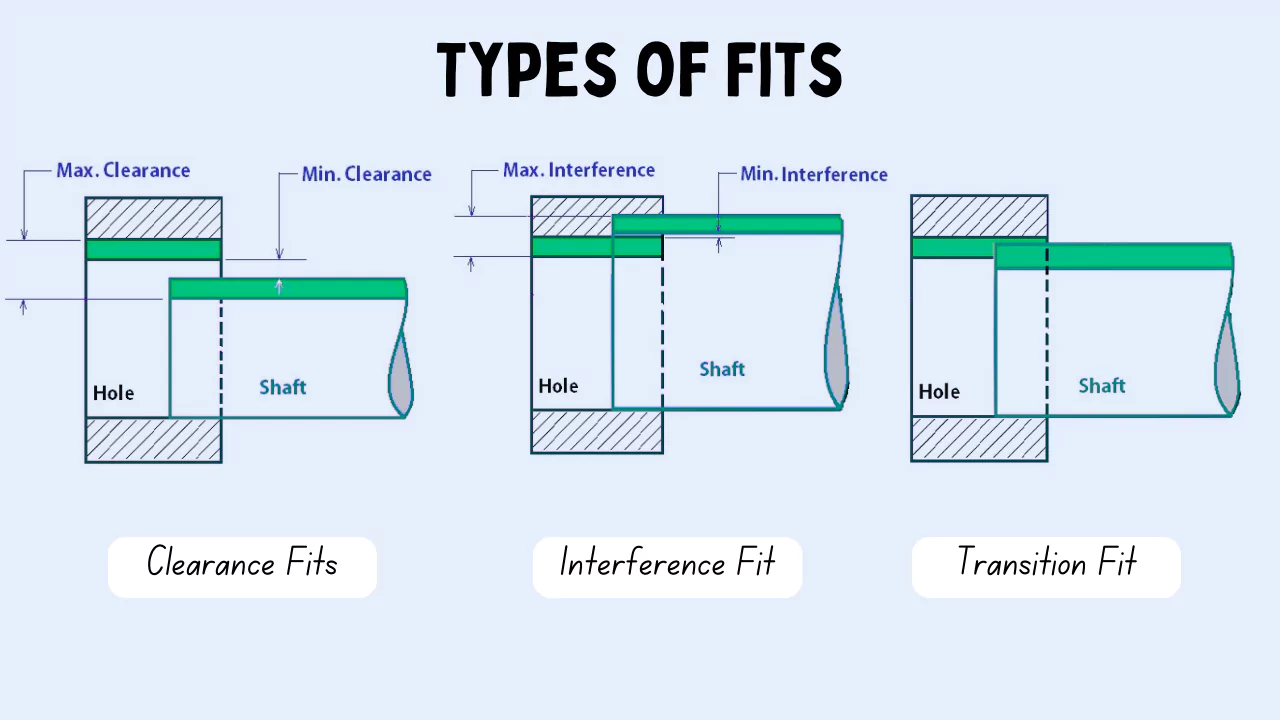
#1. Interference Fit.
The interference fit is a type of engineering fit where high frictional force tightly holds the mating surfaces together. Consequently, the interference fit is also known as a friction fit.
The tightness of interference fits comes from its negative clearance. This means that the mating surfaces press into each other. In other words, the mating surfaces deform inwards under contact pressure. For instance, in a hole and shaft system, the hole is smaller than the shaft in an interference fit. The shaft is forcefully press-fit (another name for interference fit) into the hole via a hydraulic press or hammers.
Additionally, another common method to create interference fits is by shrink-fitting. In this technique, one of the parts is either cooled or heated so that it contracts or expands+ (respectively) enough for the negative clearance to momentarily change to positive clearance. After locating the parts against each other, the temperatures normalize. The resulting thermal shrinkage/expansion creates a tight interference fit.
Generally, the clearance in an interference fit is -0.001mm to -0.042mm. Now, let’s see the sub-categories of interference fit:
- Press Fit: A lighter variant of press fitting with minimal negative clearance for medium-strength joints.
- Driving Fit: Medium interference joint that can carry loads and requires cold/hot pressing and force to assemble.
- Forced Fit: Forced fits are the strongest type of engineering fit. They require cold/hot pressing and are almost always permanent. Their assembly warrants careful tolerancing and placement to avoid the breakage of parts.
#2. Clearance Fit.
A clearance fit has a positive allowance. This means that there is a slight gap between the mating surfaces. As a result, the parts also have some play, but it is negligible and often not observable to the naked eye.
Due to this play, parts in a clearance fit have a certain degree of freedom (of movement). For example, the pin and frame in pivot joints have a clearance fit, allowing both components to move independently of each other but also stay locked in place at the same time.
The common range of clearance in these engineering fits is +0.025mm to +0.089mm. A summary of the clearance fit types is as below:
- Loose Running: The clearance is set at the higher end of the range given above. Parts in a loose running clearance fit are free to rotate/slide and have an observable play.
- Free Running: Similar to a loose running joint. Parts can move at high speeds and the joint can accommodate thermal expansion. However, the location accuracy is low due to considerable play.
- Close Running: Close running fits have a slightly better positioning accuracy and allow parts to move even at high temperatures and speeds.
- Sliding: Sliding joints are high-accuracy engineering fits. Clearance is kept to a minimum to restrict all degrees of freedom except in the sliding direction.
- Location: Location fits are very high-precision fits to locate the mating parts accurately. The clearance is very low and requires lubrication to allow smooth motion.
#3. Transition Fit.
Transition fit is a middle ground between the other two engineering fits. Depending on the application, the mating parts can have either a small interference or clearance.
If there is a negative interference, like an interference fit, the pressure and load-carrying capacity is not that high. If there is a clearance, as with a clearance fit, there is not as much play.
Typically, a transition fit is useful for precision-locating parts in assembly operations. It restricts their relative movements while also preventing extreme mechanical stresses.
The mechanical interference/clearance in transition fit ranges between +0.023mm to -0.018mm. Furthermore, transition fit has two common types:
- Similar Fit: A very light engineering fit with near-zero clearance/interference. Generally, a human-applied force with a mallet is sufficient to achieve the fit.
- Fixed Fit: Slightly tighter than a similar fit that requires a press to achieve.
How to Choose the Right Fits in Engineering
Choosing the right type of fit for your projects depends on understanding several factors. Below are the important factors that you should watch out for:
Application
Based on what you need, there are different types of fits ideal for different kinds of purposes. By going through properties such as accuracy, tolerance, exhibited by the different types of fits and the product’s proposed function, you should be able to decide on the right fits for a project.
Budget
Before deciding on the right types of fit for your products, you should know your budget. For example, using fits with tighter tolerances will cost more than normal. Therefore, you must weigh your options carefully. It would be best to get a fit that delivers the right tolerance needed to perform its functions while reducing product development costs.
Tolerance
You must understand the concept of tolerance of a product to choose the right types of fits for such a product. You have to be specific about what you want. Also, you must also answer questions such as whether you want the components to rotate in a full circle or want them to be tight?
Another thing you also need to be careful about is the tolerance slack, which is the total maximum or minimum tolerance of a particular measurement. For example, you have to be careful about the aggregation of different parts’ tolerance to make up a single product. This is very important if the resulting tolerance is very high.
FAQs
What are 3 types of FITS?
There are three types of fit commonly referenced in manufacturing and mechanical engineering.
1. Clearance Fit. Clearance fits allow for loose mating, where free movement is important and a certain amount of play is desired.
2. Interference Fit. An interference fit will be much tighter than a clearance fit.
3. Transition Fit. A transition fit would fall between a clearance and interference fit.
What is a H7 fit?
For example, in H7/h6 (a commonly-used fit) H7 represents the tolerance range of the hole and h6 represents the tolerance range of the shaft. These codes can be used by machinists or engineers to quickly identify the upper and lower size limits for either the hole or shaft.
What is the difference between fit and FITS?
The past/past participle form of the verb fit is normally fit. The first sentence is in the past, so the “fit” has been used in the sentence as the past form, not the present form. If you want to form the sentence in the present, you can use fits as follows: I am wondering if it fits you.
What is a wringing fit?
Wringing fit: Wringing fit is used when the parts need to be replaced without any difficulty. A common example is the assembly of pulleys on a drive shaft and a driven shaft.
What are the classification FITS?
Both ISO and ANSI have standardised fits in three classes – clearance, transition and interference. Each class has a variety of options available for choosing the correct one for a specific application.