In mechanical engineering, tolerances set the allowable deviation from assigned dimensions. The use of tolerances helps to ensure that the final product is readily usable, especially if it is a part of a larger assembly.
Not setting a tolerance in a critical area may render the part unusable according to the design intent, as each fabrication method comes with a certain level of inaccuracy.
However, pinpointing a suitable tolerance makes sure that the manufacturing company knows to tackle a few specific points in the production process with more attention. This can be the difference between perfectly mating parts and scrap metal.
What is Tolerance in Engineering?
Tolerance is the total amount a dimension may vary and is the difference between the upper (maximum) and lower (minimum) limits. Because it is impossible to make everything to an exact size, tolerances are used on production drawings to control the parts.
In particular, tolerances are assigned to mating parts in an assembly. For example, in case, when the slot in the part must accommodate another part. One of the great advantages of using tolerances is that it allows for interchangeable parts, thus permitting the replacement of individual parts.
Tolerances can be expressed in several ways:
- Direct limits, or as tolerance values applied directly to a dimension.
- Geometric tolerances, indicated by special symbols related to part surfaces.
- Notes referring to specific conditions, usually placed next to the corresponding dimensions. Example: single limit tolerance which limits either the maximum or minimum size of a feature or a space, leaving the other limit of size unspecified.
- A general tolerance note in the title block.
General tolerances are given in a note or as part of the title block. A general tolerance note would be like: All decimal dimensions to be held to ± .002″
This means that a dimension such as .500 would be assigned a tolerance of ± .002, resulting in an upper limit of .502 and a lower limit of .498.
For metric dimensions, the note would be similar: All metric dimensions to be held to ± 0.05
This means that a dimension such as 65.00 would be assigned a tolerance of ± 0.05, resulting in an upper limit of 65.05 and a lower limit of 64.95.
In this method, the dimension applied to each feature automatically identifies the required tolerance. Actual tolerances may vary from one company to another, but the ones given here are common tolerances for machined parts.
General tolerances may contain just one set of figures if all dimensions have the same number of decimal places.
If a dimension has a tolerance added directly to it, that tolerance supersedes the general tolerance note. A tolerance added to a dimension always supersedes the standard tolerance, even if the added tolerance is larger than the standard tolerance.
Direct Limits
Tolerances can be applied directly to dimensioned features, using limit dimensioning. This is the ASME preferred method; the maximum and minimum sizes are specified as part of the dimension.
Either the upper limit is placed above the lower limit, or when the dimension is written in a single line, the lower limit precedes the upper limit, and they are separated by a dash or by a slash: 3.49-3.53 or 3.49/3.53.
Plus, and Minus Tolerances
With this approach the basic size is given, followed by a plus/minus sign and the tolerance value.
Tolerance can be unilateral or bilateral. A unilateral tolerance varies in only one direction, while a bilateral tolerance varies in both directions from the basic size.
If the variation is equal in both directions, then the variation is preceded by a + symbol. The plus and minus approach can only be used when the two variations are equal.
Important terms
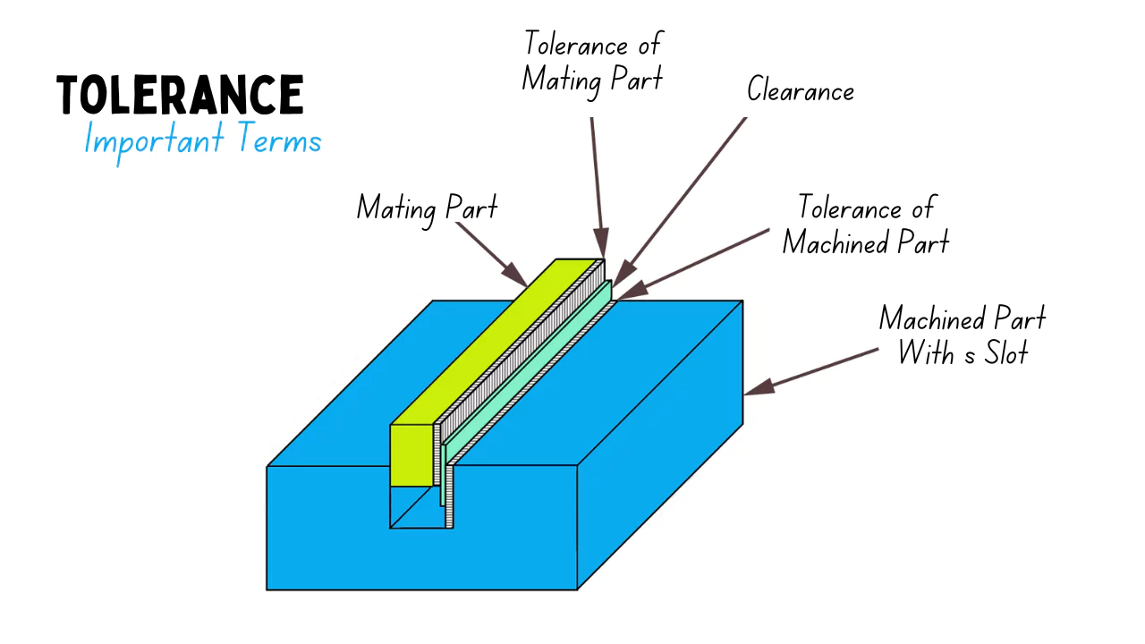
The figure shows a system of two machined parts with slot and mating parts that have toleranced dimensions. These two parts are used as examples in ASME/ANSI standard to define important terms.
- Nominal Size – a general size, common fraction.
- Basic size – the theoretical size used as a reference for the application of tolerances. This size is shown o the drawings in a rectangular box.
- Actual size – actual measured size of the finished part after machining.
- Limits of size – the maximum and minimum permissible sizes between which the actual size should lie. The larger value for each part is the upper limit, and the smaller value is the lower limit.
- Allowance is the minimum clearance or maximum interference between parts, or the tightest fit between two mating parts.
Considerations when setting tolerances
A primary concern is to determine how wide the tolerances may be without affecting other factors or the outcome of a process. This can be done by the use of scientific principles, engineering knowledge, and professional experience. An experimental investigation is very useful to investigate the effects of tolerances: Design of experiments, formal engineering evaluations, etc.
A good set of engineering tolerances in a specification, by itself, does not imply that compliance with those tolerances will be achieved. The actual production of any product (or operation of any system) involves some inherent variation of input and output.
Measurement error and statistical uncertainty are also present in all measurements. With a normal distribution, the tails of measured values may extend well beyond plus and minus three standard deviations from the process average. Appreciable portions of one (or both) tails might extend beyond the specified tolerance.
The processing capability of systems, materials, and products needs to be compatible with the specified engineering tolerances. Process controls must be in place and an effective Quality management system, such as Total Quality Management, needs to keep actual production within the desired tolerances.
A process capability index is used to indicate the relationship between tolerances and actual measured production.
The choice of tolerances is also affected by the intended statistical sampling plan and its characteristics such as the Acceptable Quality Level. This relates to the question of whether tolerances must be extremely rigid (high confidence in 100% conformance) or whether some small percentage of being out-of-tolerance may sometimes be acceptable.
Types of Tolerances
Today, there are 14 types of geometric tolerances by the number of symbols, and 15 types based on classification.
These are grouped into Form tolerance, Orientation tolerance, Location tolerance, and Run-out tolerance, which can be used to indicate all shapes.
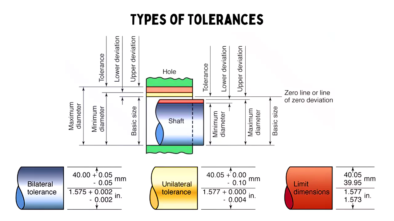
Following are the three types of tolerances used in measurements:
- Unilateral tolerances
- Bilateral tolerances
- Compound tolerances.
1. Unilateral Tolerances
When the two limit dimensions are only above the nominal size as shown in the figure or only below the nominal size then the tolerance is said to be unilateral.
2. Bilateral Tolerances
When the two-limit dimension is above and below the nominal size, Then the tolerances are said to be bilateral.
3. Compound Tolerances
Compound tolerance is determined by the established tolerances i.e., the combination of more than one type of tolerances are called compound tolerances, the different types of tolerances may be angular, lateral, etc.
For Example: In figure tolerances on dimension/are dependent on tolerances of L, h, and θ. This compound tolerance on ‘l’ is the combined effect of these three tolerances. The minimum tolerance on ‘l’ will be corresponding to L-b, θ+∝ , and h+c.
Fits
Engineered products may sometimes be parts of an assembly that must fit or slip into each other to function. As such, a fit pertains to the dimensional relationships shared by the components of an assembly or the hole with the same basic size and the shaft’s tolerance zone. It determines if the components are tight or loose.
Various options are involved in both the shaft and hole matings, and they often require the appropriate mechanical tolerances to attain the right fit. Other factors, such as ease of assembly, prevailing environmental conditions, and required precision, are fundamental to engineering components for assembly.
Common Types Of Fits
According to ISO, there are different fit types in mechanical engineering. Each fit is suitable for different circumstances. Below are these fit types:
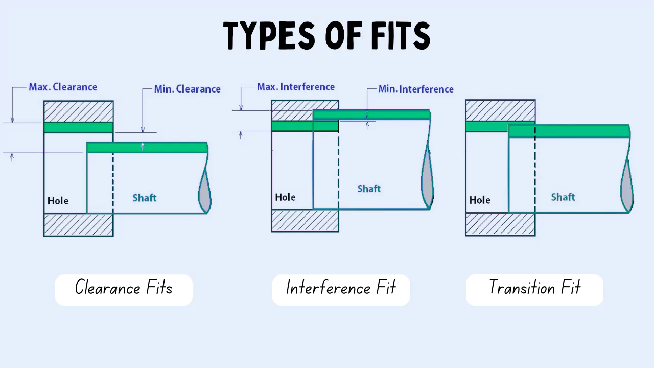
Clearance Fit
A clearance fit is designed for situations that require loose mating and free movement of components. Hence, they are suitable for making products in which components of their assembly must slide in and out easily. Moreover, clearance fits support relative movement between two components joined in an assembly.
The shaft diameter is usually smaller than the hole, resulting in two conditions. One is the minimum clearance in which the diameter of the shaft is higher while the hole has the minimum diameter. Secondly, a maximum clearance in which the hole bears the maximum diameter while the shaft has the minimum diameter.
Interference Fit
Interference fit (also called friction fit or press fit) aids the assembly of two components by pushing them together. The fastening occurs using different mechanisms, such as substantial force for physical fitting. Also, the mechanism decides the various categories of interference fits to employ. The press-fitting of a bearing into a housing is an apt example of interference fit.
The maximum interference is the difference between the hole’s minimum size and the maximum shaft size. Similarly, the minimum interference is the difference between the minimum shaft size and the maximum size of the hole.
Transition Fit
Transition fits provide a balance between interference fits and clearance fits. They are suitable for situations where manufacturing accuracy is a priority. For example, these fits are perfect for assembly where the mating parts must be connected with higher precision.
A good example is fitting a piston into a cylinder. The diameter of the piston is less than the cylinder bore, making a minor clearance to aid assembly while ensuring enough interference for proper fastening and stability.
Product engineers and machinists often call this fits slip or push fit. Moreover, transition fits possess minor clearance, ensuring simplified assembly while offering some interference to improve balance and stability. As such, it is evident that transition fit is the ideal engineering solution when your design requires a secure connection and easy assembly.
FAQs
What is meant by tolerance in engineering?
Tolerance is the total amount a dimension may vary and is the difference between the upper (maximum) and lower (minimum) limits. Because it is impossible to make everything to an exact size, tolerances are used on production drawings to control the parts.
Why is engineering tolerance important?
Because it is impossible to make everything to an exact size, tolerances are used on production drawings to control the parts. When do we need tolerances? In particular, tolerances are assigned to mating parts in an assembly. For example, in case, when the slot in the part must accommodate another part.
What does high tolerance mean in engineering?
A high tolerance means the allowable variation from the nominal or target dimension is very small. In other words, the manufactured part must closely match its design specifications with minimal standard deviation.
What is the importance of tolerance in electrical engineering?
In engineering, tolerance is important because some variation in manufactured goods is normal and expected. Calculating the amount of allowable variance saves time, materials, and money while still engineering high-quality products.
How to find tolerance in engineering?
1. Calculating Total Tolerance.
2. Total Part Tolerance = Upper Limit – Lower Limit.
3. Calculating Fit between Two Objects.
4. Allowance = Lower Limit of the Hole – Upper Limit of the Pin.
NOTE: Formula should always start as stated in order to get correct outcomes.
5. Positive (+) Allowance = Clearance.
What is a tight tolerance in engineering?
Tight tolerance can mean something different depending on the molder, but it is generally recognized as ± 0.002 inches, and very tight tolerance is ± 0.001 inches. Part complexity, material, manufacturing processes, and tooling all impact the tolerances that can be achieved.